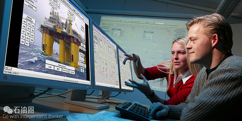
高压操作的危险系数极高,压力过载引起的事故将对环境、设备及工作人员造成巨大的伤害,这是任何人都不希望看到的灾难。降低生产井及油气输送设施压力风险重要性不言而喻,油田开发商对于此类操作系统一直有强烈的诉求,为此,Cameron带来了完美解决方案—HIPPS。
HIPPS是Cameron开发的一款压力设备完整性保护系统,具有独立的操作系统,相对于常规的紧急关停系统可靠性更高。HIPPS同时满足海上和陆地油田对生产及储运设备的压力控制要求,通过监测和控制设备压力,防止其超过系统设定的极限值,降低系统发生危险的概率。石油圈原创www.oilsns.com
HIPPS采用Cameron公司成熟的阀门、触发器工艺,例如符合API 6A标准的FLS平板阀和GROVE球阀,气控和液压控制触发器包括Saf-T-Gard MH和LEDEEN系列,目前HIPPS系统已经通过了SIL3认证。在应用中,HIPPS通常作为油田高压设备与低压设备之间的过渡段,是一道可靠的屏障。
HIPPS是Cameron对其产品有效整合的结果,HIPPS操作、控制系统独立,在油气开采的各个阶段都能发挥巨大作用。该系统主要包括三个模块:阀门、触发器/控制装置、逻辑解算器。为了满足不同的应用,Cameron提供多种配置的HIPPS系统,包括独立的机械及电子控制程序。
液压HIPPS系统石油圈原创www.oilsns.com
液压(机械)HIPPS系统是一种独立的自控制系统,主要结构包括压力传感器(1oo2模式)、液压解决方案和两个弹簧控制-液压触发安全阀。HIPPS无需外配电源,本身发电量即满足应用要求,根据具体情况还可配置实时控制系统(HPU)。
在正常工作情况下,HIPPS为安全阀门提供压力,使其保持打开状态,直至系统检测到设备压力发生异常。当HIPPS检测到设备压力出现异常,即可立即触发两个安全阀,保护后续设备不受损坏。
(注:1oo2—同时有两个传感器,当有任何一个达到警报值时,触发器即触发;2oo3—同时有三个传感器,当有任意两个达到警报值,触发器触发)
电子控制HIPPS系统石油圈原创www.oilsns.com
电子HIPPS系统也是一种独立控制的设备压力完整性保护系统,主要包括压力发射器(2oo3模式)、电子逻辑解算器和两个弹簧控制-液压触发安全阀。该系统既可使用外带电源,也可使用手动控制泵/HPU进行自身发电提供能量。
HIPPS工作原理石油圈原创www.oilsns.com
HIPPS的主要功能是检测压力异常情况,之后自动打开隔离阀,保护后续设备不受损坏。如上文提到那样,HIPPS是一个完全独立的操作系统,与油田生产设施的过程控制关停系统(PSD)、紧急关停系统(ESD)以及控制系统互不干扰。石油圈原创www.oilsns.com
HIPPS不只是一个检测压力异常、自动关闭阀门的保护系统,还可以根据需要配置其他功能,比如监测设备动力信号等。通常情况来说,HIPPS通过检测信号异常做出各种决策,比如仪表气源丢失、液压不足、电压不足或是设备信号缺失等,各种信号在决策过程中均保持独立性,不会互相干扰。为了提高作业的安全性,HIPPS还具有冗余设计,最大化系统适用性和设备稳定性。
安全仪表系统(SIS)石油圈原创www.oilsns.com
SIS是一种有效防止事故发生、降低事故发生几率的控制程序,在设备发生异常时,SIS会根据预先设定的处理方案将异常状况平复。在应用中,SIS有多种形式,包括ESD、安全锁系统、安全关停系统等,而每一种SIS都具有完整的安全仪表功能(SIFs)。
SIF系统都包括逻辑解算器、传感器、电磁阀以及终端控制模块(如自动控制阀)。SIS定义内的SIF系统具有一个完整性安全等级(SIL)模块,根据失效概率(PFD)衡量生产设施的运行状态。根据设备及流程的不同,SIL可能会有略微差别,但是对于一个完整系统而言,每个安全模块的SIL也不必完全相同。
一般情况下,HIPPS系统包含两个ESD阀门、1oo2模式逻辑解算器、3个2oo3模式压强传送器。具体组成模块如下:
- 压力、流速传感器有1oo2或/和2oo3两种模式;石油圈原创www.oilsns.com
- 逻辑解码器可高效处理传感器数据,是HIPPS系统的决策依据;
- 满足SIL 3标准的决策模块,保证系统处于安全运行状态,杜绝高压隐患。
相对于常规PSD和ESD系统,HIPPS独立仪表系统的完整性更高,该系统可满足陆地及海上油田的压力等级控制要求,保持生产设备完整性。
小编手中还握有HIPPS完整性保护系统等相关产品的更多资料哦,想获取?很简单:请将此文章分享至朋友圈,并向小编秀出朋友圈分享截图,小编会将资料打包奉上,发送至您的邮箱!还有机会与技术专家沟通交流哦~
来自/Cameron 译者/张德凯 编辑/Leia
When operating in high-pressure environments and production fields, an overpressure event can cause damage to the environment, infrastructure, and personnel. Mitigating that risk on production wells and flowlines is a challenge that can be met with a HIPPS.
The Cameron high integrity pressure protection system (HIPPS) is an independently instrumented system designed with higher integrity than process shutdown and emergency shutdown systems. Suitable for onshore and offshore installations requiring high integrity pressure protection of downstream systems, HIPPS is used to prevent a system from exceeding its rated pressure level. The HIPPS is SIL3 certified and incorporates our field-proven valves and actuators, such as FLS* extreme service API 6A slab-style gate valves and GROVE* valves. Pneumatic and hydraulic actuators such as Saf-T-Gard MH Series hydraulic piston actuators and LEDEEN* actuators are supplied. A HIPPS system is considered the barrier between the high and low pressure sections of an installation or production facility.
The HIPPS system combines Cameron products into an independent, stand-alone system for any application within the oil and gas industry. HIPPS systems consist of three elements — valves, actuators and controls, and a logic solver. Cameron provides HIPPS systems in a variety of configurations, including mechanical and electronic standalone packages.
Hydraulic HIPPS
The intended use of the hydraulic (mechanical) HIPPS system is to provide a self-contained independent protection system operated in the demand mode with one out of two voting pressure sensor inputs, hydraulic logic solver, and two spring return hydraulically actuated safety valves. The unit is typically self-powered and can be provided with additional real-time controls (HPU). This pressurizes the system and opens the safety shutdown valves. The system remains open (armed) until an abnormal condition is detected. Once an abnormal condition is detected, the system closes the two actuated final element valves protecting the downstream production or facility.
Electronic HIPPS
The intended use of the electronic HIPPS system is to provide a self-contained independent high protection system operated in the demand mode with two out of three voting pressure transmitter inputs, electronic logic solver, and two spring return hydraulically actuated safety valves. The unit can be self-powered with a manual hand pump/HPU, and can also be configured to operate using facility power sources. This pressurizes the system and opens the safety shutdown valves. The system remains open (armed) until an abnormal condition is detected. Once an abnormal condition is detected, the system closes the two actuated final element valves protecting the downstream production or facility.
How a HIPPS Works
The primary function of HIPPS is to detect high-pressure conditions and close isolation valves to protect lower-rated downstream infrastructure. The system operates autonomously and is independent of the facilities’ process shutdown (PSD), emergency shutdown (ESD), or control systems. HIPPS are fail-close by design based on the signal of an overpressure event and can be configured to operate on other events, such as a loss of motive power of instrument signal. It is typically fail-close for any loss of instrument air, hydraulic power, electric power, or instrument signals. Each HIPPS loop is independent. A HIPPS is designed with redundant safety functions to reduce the risk of failure on demand and to maximize availability.
Safety Instrumented Systems
A safety instrumented system (SIS) prevents or reduces hazardous events by taking a process to a safe state when predetermined conditions are met. An SIS can be an ESD, safety interlock system, or safety shutdown system. Each SIS has one or more safety instrumented functions (SIFs).
Each SIF loop is a combination of logic solvers, sensors, solenoids, and final control elements, such as an automated valve. Every SIF within an SIS will have a safety integrity level (SIL), which is a measure of the system performance in terms of probability of failure on demand (PFD). These SIL levels may be the same or may differ depending on the process. An entire system does not need to have the same SIL level for each safety function.
The Cameron HIPPS comprises two ESD valves, a 1oo2 logic solver, and typically three pressure transmitters with 2oo3 voting logic.
Components include:
- sensors that detect high pressures or flow rates 1oo2, 2oo3, or both;
- logic solver that processes the input from the sensors to the final element;
- SIL 3 rated final elements that bring the process to a final safe state, isolating the source of overpressure.
The Cameron HIPPS is an independently instrumented system designed with higher integrity compared with PSD and ESD systems. Suitable for onshore and offshore installations requiring high-integrity pressure protection of downstream systems, a HIPPS is used to prevent a system from exceeding its rated pressure level. The Cameron HIPPS is SIL 3 certified and incorporates our field-proven valves and actuators, such as the FLS* extreme service API 6A slab-style gate valve and GROVE* valves. Pneumatic and hydraulic actuators, such as the Saf-T-Gard* MH Series hydraulic piston actuators and LEDEEN* actuators, are supplied. A HIPPS is considered the barrier between the high- and low-pressure sections of an installation or production facility.
The HIPPS combines Cameron products into an independent, stand-alone system for any application within the oil and gas industry. Cameron provides the systems in a variety of configurations, including mechanical and electronic standalone packages.
未经允许,不得转载本站任何文章:

 石油圈
石油圈
